Sealing Jaws & Bars
Bar, jaw and contact geometry, fixing dimensions and film interface, matched to the required seam.
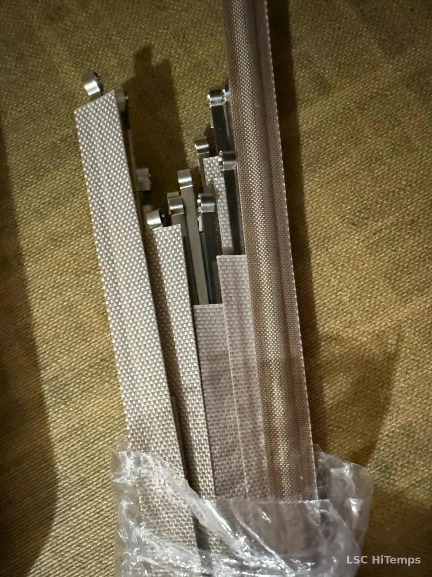
Sealing jaws, impulse bands, NiCr elements and PTFE-insulated strips engineered as a complete electrical and mechanical interface — from the existing part, drawing or machine reference.
LSC starts with contact geometry, sealing duty and the original machine circuit. The aim is a qualified replacement, not a nominally similar strip.
Bar, jaw and contact geometry, fixing dimensions and film interface, matched to the required seam.
Flat or formed resistive elements for sealing, simultaneous seal-and-cut, trimming and cutting.
Cold-zone lengths, insulation and terminal geometry designed with the active element and machine connection.
These three simplified LSC sketches show functional principles, not manufacturer profiles or dimensional specifications.
Broad, continuous heat/contact footprint for an impulse seam.
A raised or focused profile for simultaneous joining and material separation.
Concentrated thermal contact for cutting or edge trimming.
The active resistive span sits between low-resistance end zones. Overall length, cold-zone extent and terminal geometry must be dimensioned independently.
LSC original schematic, not to scale. Final lengths and transition geometry require the original component or a dimensioned drawing.
Define the alloy, diameter or width × thickness, resistance per metre, active length and allowable machine electrical load together. Supply can be stock resistance material or finished machine-specific elements.
Existing LSC technical examples: flat strip 3.0 × 0.20 mm; other sections from drawing or sample. Illustrative only.
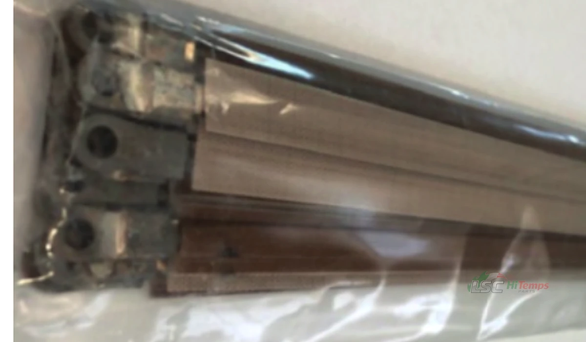
A flat resistive element may be fitted with PTFE sleeve/tube insulation, controlled active and overall lengths, coppered low-resistance ends, and eyelet, crimped, soldered or special terminals.
A 6.0 × 0.30 mm flat strip appears in existing LSC reference material; the final section must be machine-checked.
Original LSC line symbols illustrate common connection families. Hole centres, thickness, fixing and electrical contact must match the existing circuit and mounting.
Hole centre, outside width and connection method.
Thickness, width and conductive mating area.
Mechanical retention and electrical contact under load.
Bent, welded or soldered geometry from a sample.
Coppered low-resistance ends and further coatings are options to assess for each connection — not universal part specifications.
Defined low-resistance termination zones and transition lengths.
Possible additional corrosion/storage protection when contact suitability is confirmed.
Possible contact finish for selected precision/control applications, subject to qualification.
Machine/model, drawing or sample, total and active lengths, width/thickness/section, terminals, circuit data if known and quantity.
Existing technical URLs remain available for continuity: